Photochemical Metal Etching
Utilizing Computer Aided Design (CAD)
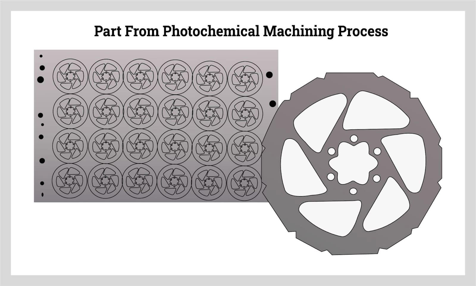
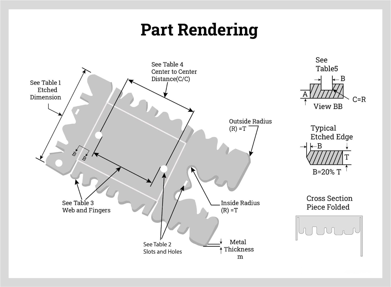
The process of photochemical metal etching begins with the creation of a design using CAD or Adobe Illustrator. Although the design is the first step in the process, it is not the end of computer calculations. Once the rendering is finished, the thickness of the metal is determined as well as the number of pieces that will fit on a sheet, a necessary factor for lowering the cost of production. A second aspect of the thickness of the sheet is a determination of part tolerances, which hinge on the part dimensions.
The process of photochemical metal etching starts with creating a design using CAD or Adobe Illustrator. However, this is not the only computer calculation involved. After completing the design, the thickness of the metal is determined, as well as the number of pieces that can fit on a sheet to reduce production costs. Additionally, the part tolerances depend on the part dimensions, which also factor into the thickness of the sheet.
Metal Preparation
As with acid etching, the metal has to be thoroughly cleaned prior to being processed. Each piece of metal is scrubbed, cleaned, and cleansed using water pressure and a mild solvent. The process eliminates oil, contaminants, and tiny particles. This is necessary to provide a smooth clean surface for the application of the photoresist film to securely adhere.
Laminating Metal Sheets with Photoresistant Films
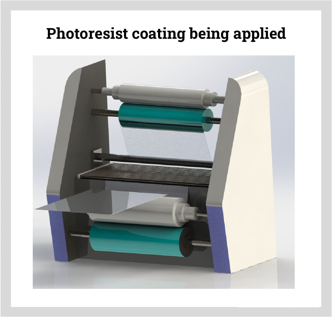
Lamination is the application of the photoresist film. The metal sheets are moved between rollers that coat and evenly apply the lamination. To avoid any undue exposure of the sheets, the process is completed in a room lit with yellow lights to prevent UV light exposure. Proper alignment of the sheets is provided by holes punched in the edges of the sheets. Bubbles in the laminated coating are prevented by vacuum sealing the sheets, which flattens the layers of laminate.
To prepare the metal for photochemical metal etching, it must be thoroughly cleaned to remove oil, contaminants, and particles. Each piece of metal is scrubbed, cleaned, and washed with a mild solvent and water pressure to ensure a smooth, clean surface for the application of the photoresist film.
The next step is lamination, which involves applying the photoresist film to the metal sheets. The sheets are moved between rollers to evenly coat and apply the film. The process is carried out in a yellow-lit room to prevent UV light exposure. Holes punched in the edges of the sheets provide proper alignment, while vacuum sealing flattens the layers of laminate and prevents bubbles from forming.
Photoresist Processing
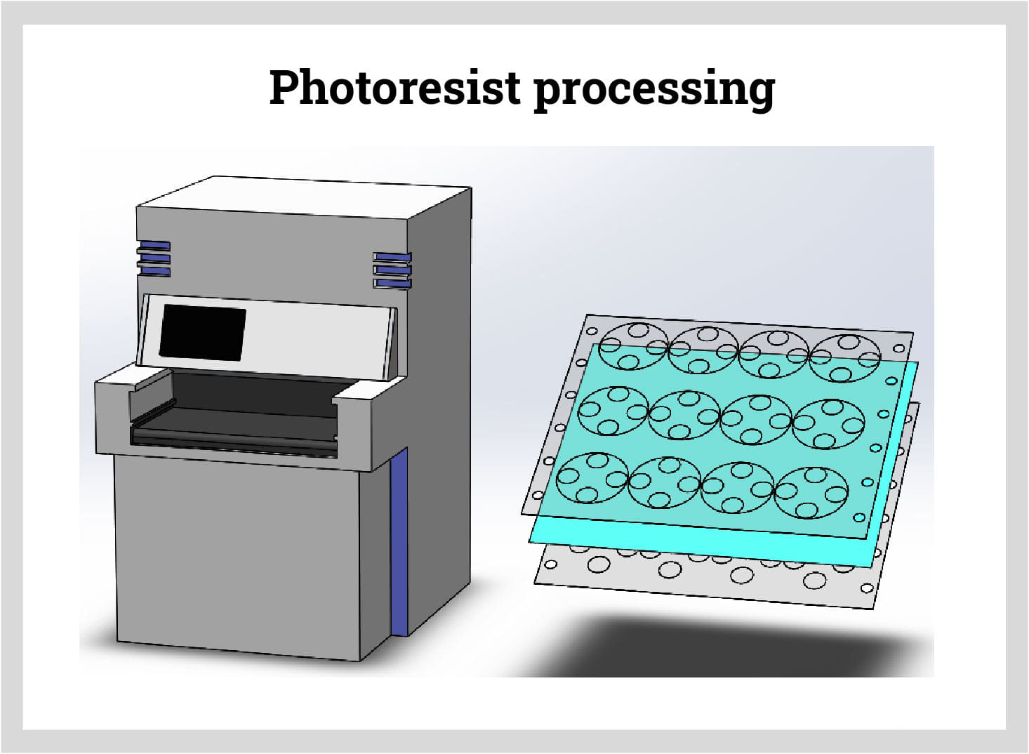
During photoresist processing, the images from the CAD or Adobe Illustrator rendering are placed on the layer of photoresist on the metal sheet. The CAD or Adobe Illustrator rendering are imprinted on both sides of the metal sheet by sandwiching them over and under the metal. Once the metal sheets have the images applied, they are exposed to UV light that places the images permanently. Where the UV light shines through the clear areas of the laminate, the photoresist becomes firm and hardens. Black areas of the laminate remain soft and uninfluenced by the UV light.
In the photoresist processing stage of photochemical metal etching, the images from the CAD or Adobe Illustrator design are transferred onto the layer of photoresist on the metal sheet. This is done by sandwiching the design over and under the metal sheet. Once the images are applied to the metal sheet, it is exposed to UV light, which makes the images permanent.
During the UV exposure, the clear areas of the laminate allow the UV light to pass through, causing the photoresist to harden and become firm. In contrast, the black areas of the laminate remain soft and unaffected by the UV light. This process creates a pattern that will guide the etching process, where the hardened areas will remain and the soft areas will be etched away.
Developing the Sheets
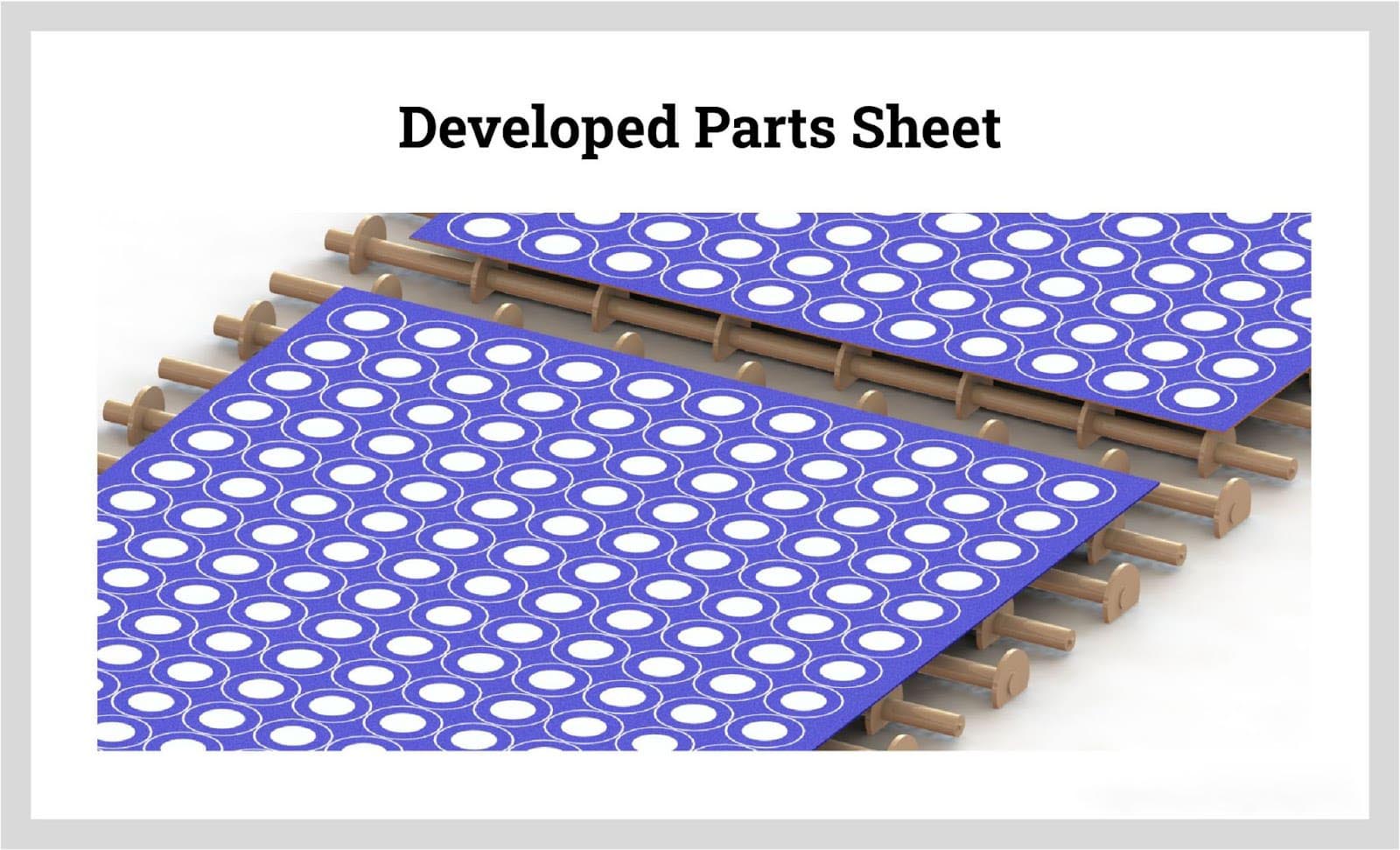
From photoresist processing, the sheets move to the developing machine that applies an alkali solution, mostly sodium or potassium carbonate solutions, that washes away the soft photoresist film leaving the parts to be etched exposed. The process removes the soft resist and leaves the hardened resist, which is the part to be etched. In the image below, the hardened areas are in blue, and the soft areas are gray. The areas not protected by the hardened laminate are exposed metal that will be removed during etching.
After the photoresist processing stage, the metal sheets are then transferred to the developing machine where an alkali solution, typically sodium or potassium carbonate, is applied. This solution washes away the soft photoresist film, leaving the parts that need to be etched exposed.
As a result, the soft resist is removed, while the hardened resist, which corresponds to the areas that need to be etched, is left behind. In the resulting pattern, the hardened areas are shown in blue, and the soft areas are gray. The areas that are not protected by the hardened resist represent the exposed metal that will be removed during the etching process.
Etching
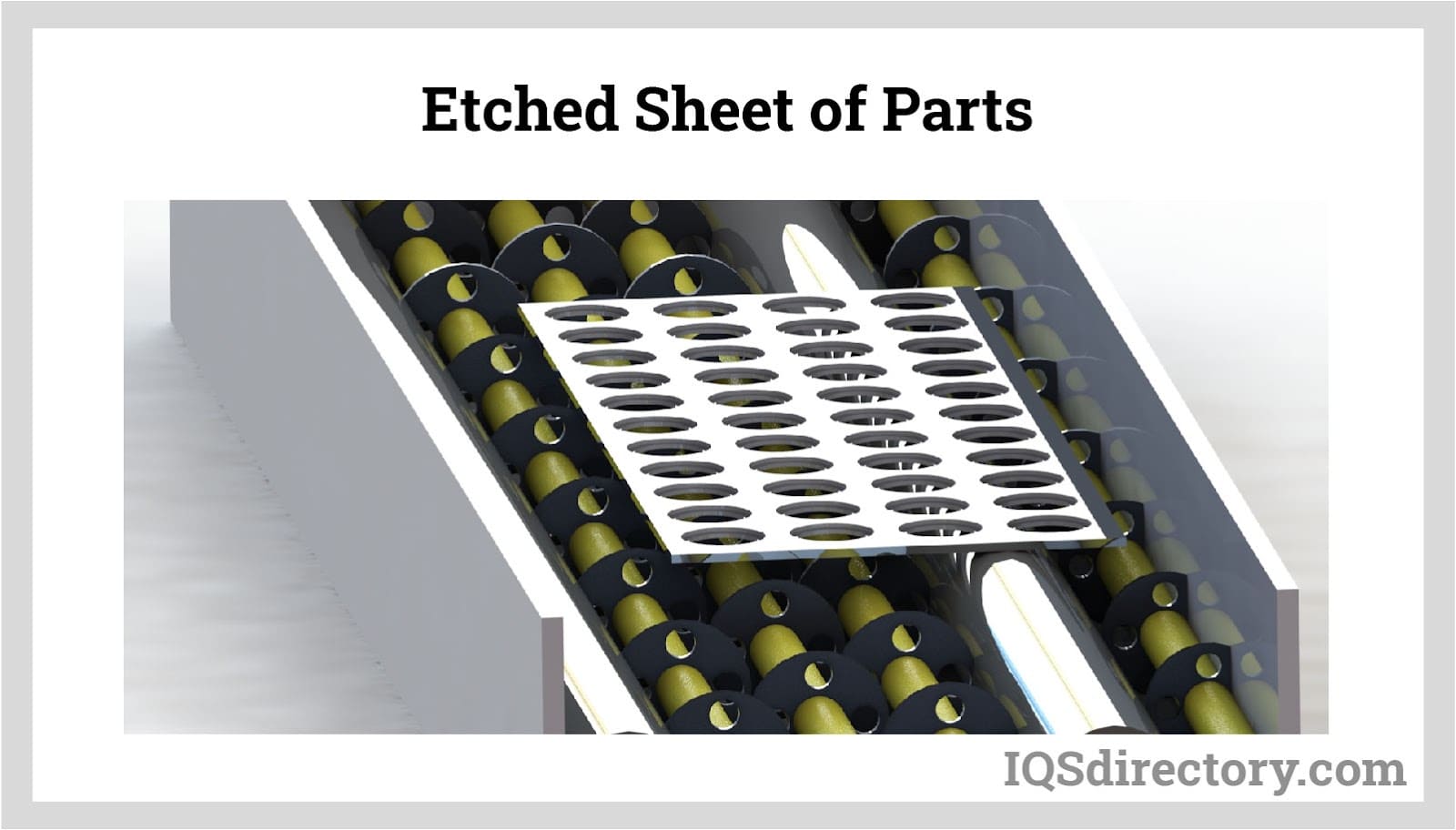
Much like the acid etching process, the developed sheets are placed on a conveyor that moves the sheets through a machine that pours etchant on the sheets. Where the etchant connects with the exposed metal, it dissolves the metal leaving the protected material.
In most photochemical processes, the etchant is ferric chloride, which is sprayed from the bottom and top of the conveyor. Ferric chloride is chosen as an etchant because it is safe to use and recyclable. Cupric chloride is used to etch copper and its alloys.
The etching process has to be carefully timed and is controlled in accordance with the metal that is being etched since some metals take longer to etch than others. For the success of photochemical etching, careful monitoring and control are crucial.
In the etching stage of photochemical metal etching, the developed metal sheets are placed on a conveyor that moves them through a machine where etchant is poured onto the sheets. The etchant dissolves the exposed metal, leaving behind the protected areas of the sheet.
Ferric chloride is commonly used as an etchant in most photochemical processes because it is safe to use and can be recycled. For copper and its alloys, cupric chloride is used instead.
The etching process must be carefully timed and controlled according to the type of metal being etched, as some metals require longer etching times than others. To ensure the success of the photochemical etching process, careful monitoring and control are crucial.
Stripping the Remaining Resist Film
During the stripping process, a resist stripper is applied to the pieces to remove any remaining resist film. Once stripping is completed, the finished part is left, which can be seen in the image below.
After the etching process, the remaining resist film on the metal sheet is stripped off by applying a resist stripper. This process removes any remaining resist film from the surface of the metal sheet.
Once the stripping process is complete, the finished metal part is left, which can be seen in the resulting image.